
SPEED
EASY NAVIGATION
QUICK RESPONSES
DIRECT SHIPMENTS
GLOBAL SUPPORT
EXCELLENCE
QUALITY SUPPLIERS
PROMPT SERVICE
SATISFACTION IS
#1 PRIORITY
ECONOMICS
LOWEST PRICES
FREE FREIGHT
QUICK DELIVERIES
KNOWLEDGE
FACTORY TRAINED
OTJ EXPERIENCE
ENGINEERING SUPPORT
Gas/Liquid Separators Explained
Design and Capabilities of Gas/Liquid Separators
![]()
Gas/Liquid separators are pressure vessels designed to remove entrained
particles and droplets from gaseous processes.
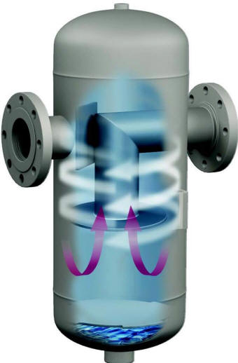
Principle of Operation
Physics Involved with our Gas/Liquid Separators
-
Centrifugal Force The internal geometry of a properly sized vessel results in centrifugal force sufficient to propel droplets and particles >10 microns to surfaces where they coalesce to a common drain.
-
-
Our gas/liquid separators have an infinite turndown ratio, meaning they
maintain their efficiency even when the flow is drastically reduced. This
is beneficial in situations where the start-up or shutdown portion of a process
results in lower flow rates.
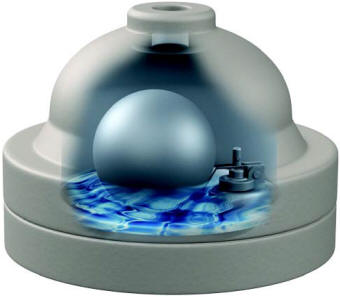
Drainage of Condensate
The condensate may be drained from the separator without loss of any
process gas using a float style drain trap. This mechanical method of
drainage simplifies installation and is extremely reliable.
Our float drain traps consist of a cast body containing a valve, valve
seat and hollow stainless steel ball ("float"). The float is connected to
the valve via a fulcrum and lever. The separated condensate drains into
the body of the drain trap, eventually causing the float to rise sufficiently
and lift the valve from its seat. The system pressure pushes against the
condensate and it drains through the drain trap outlet orifice.
Once the condensate level within the trap lowers sufficiently, the float
lowers and reseats the valve against its seat. Thus, condensate within the
float drain trap body acts as a buffer or seal, preventing any process gas from
escaping during drainage.
It is possible to use a manual or actuated valve in
conjunction with a sight gauge to achieve the same effect, however that is more
complicated and expensive for most applications.
Float drain traps have a drain port for occasional blow-down if
particulate is being removed; alternately, it may be protected with an
inexpensive Y strainer.
Since float drain traps always contain liquid condensate, special heaters
are inserted for locations where freezing is a concern.
The most common application for gas/liquid separators involves steam
systems to protect downstream equipment from condensate and pipe scale.
Compressed air systems also use multiple separators for condensate removal.
Other industries, such as oil refineries, use gas/liquid separators
throughout their process to recover product at specific temperature and pressure
points.
Gas/liquid separators are sometimes used to remove a heavy load of
particulates, resulting in a sludge-like discharge. The drain section of
the separator changes to facilitate better drainage and a rotary valve is used
to minimize loss of process gas.
The rate of liquid removal, expressed as a percentage of the process gas
weight flow, is determined by the separator size and design. The range of
removal rates vary from 5% to 90% of the weight flow. The size and
complexity of the separator design increases along with higher removal rates.
The amount of liquid to be removed affects the drain orifice size used in the
drain trap.
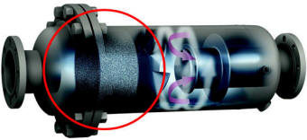
Removing droplets finer than 10 microns is possible by adding a coalescing
stage to the separator design. The coalescing stage consists of a mesh pad
for >4 micron removal. The fine droplets impinge within the mesh pad,
coalescing to >10 micron droplets which are subsequently removed by the
separation stage.
The addition of a coalescing stage requires a two-piece vessel to enable
access to the mesh pad for periodic cleaning or replacement.
It is possible to remove droplets smaller than 1 micron with the addition
of a filter element stage after the separation stage. These specially
designed borosilicate microglass filter elements have a glass matrix drainage
layer in support of retentions as fine as 0.30 microns.
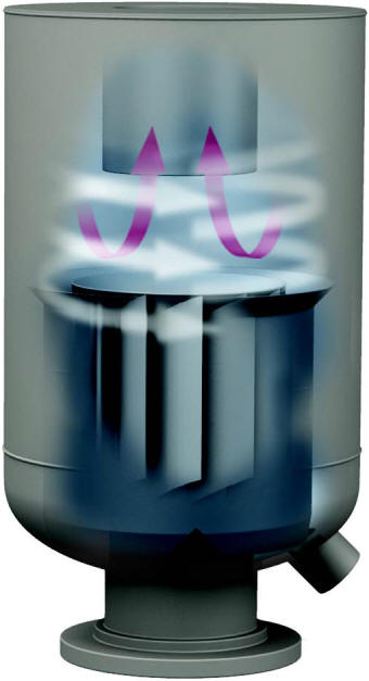
The orientation of the inlet and outlet nozzles are another customizable
characteristic to support a variety of flow paths. While horizontal piping
is commonplace, sometimes the flow path is vertically UP, vertically DOWN or
some combination of horizontal and vertical.
Exhaust Heads
An exhaust head is a special version of a gas/liquid separator used at the
end of a ventilation pipe; most commonly for steam applications although
sometimes there are exhaust systems other than steam for which it is desirable
to remove droplets >10 microns.
One side of an exhaust head is always
"open" to atmosphere, which means
that it is NOT a pressure vessel; its design pressure is atmospheric despite it
being a fully welded item having a flanged inlet matching the class of the
corresponding piping.
Exhaust heads reduce the opacity and volume of the condensate plume
exiting the exhaust pipe. Unlike a pressure vessel separator, there is no
requirement for a float drain trap and often the condensate is recycled to
reduce the consumption of boiler treatment chemicals.
Exhaust heads are sometimes referred to as "silencers" because, like a
muffler, they do reduce the exhaust sound. However, this is not their
purpose, any reduction of sound is attributed to the indirect path required for
droplet removal and thus there are no design standards for sizing exhaust heads
specifically for noise reduction.
Design Criteria
Proper sizing of gas/liquid separators requires only a few data points:
-
The molecular weight (MW) of the gas
-
The maximum temperature and the minimum pressure, even if they are mutually exclusive
-
The gas flow rate (volumetric or weight flow)
-
The existing or intended inlet pipeline size
-
The approximate amount of condensate to remove
-
The desired flow path
The initial cost of gas/separators are in many ways the final cost, given
they operate reliably for decades protecting equipment and improving process
efficiencies without need for maintenance.